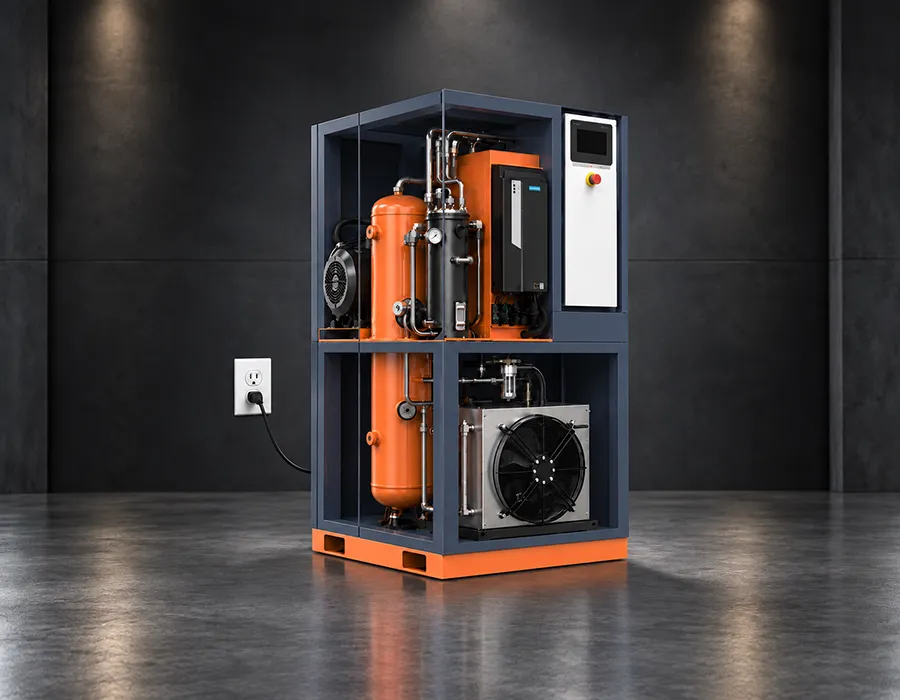
A complete screw air compressor comprises not only the airend (main unit) and motor but also systems for air intake, oil-air separation, cooling, control, and post-treatment. This article introduces the main components of a screw air compressor and their functions.
1. Airend and Motor System
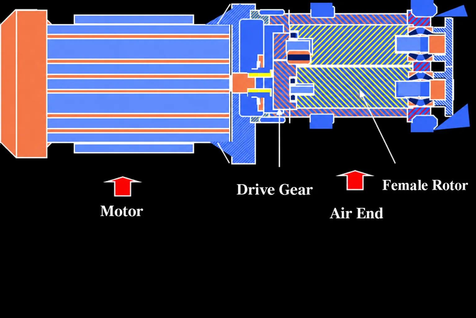
UMW Air compressors are twin-screw units featuring a pair of intermeshing rotors with helical teeth rotating in opposite directions. The rotor with convex tooth profiles is known as the male rotor, while the one with concave profiles is the female rotor. As the rotors rotate within the housing, the working volume changes continuously due to the meshing and unmeshing of the teeth; this cyclic variation of the volume between rotor tooth grooves facilitates the intake, compression, and discharge of gas.
The airend is the core component of the screw compressor; regardless of the brand, the structural design and operating principles of the airend remain similar.
Intake Process
As the rotors rotate, a tooth on the male rotor progressively disengages from a groove on the female rotor. The inter-lobe volume expands and connects to the intake port, allowing gas to enter. Once the volume reaches its maximum, it disconnects from the intake port; the interaction between the teeth and the inner housing seals the volume, concluding the intake process. Notably, at this stage, the inter-lobe volumes of the male and female rotors are not connected to each other.
Compression Process
As rotation continues—and before the inter-lobe volumes of the male and female rotors connect—the gas within the male rotor’s inter-lobe volume is initially compressed by the encroaching tooth of the female rotor. After a certain angle of rotation, the inter-lobe volumes of the male and female rotors merge to form a V-shaped pair of inter-lobe volumes (known as the elementary volume). As the teeth mesh further, this elementary volume is progressively displaced and reduced in size, thereby compressing the gas. The compression process continues until the elementary volume connects to the discharge port.
Discharge Process
As the rotors rotate, the working volume continuously shrinks, delivering the compressed gas to the discharge pipe; this process continues until the volume reaches its minimum size.
With the continuous rotation of the rotors, the aforementioned suction, compression, and discharge processes repeat cyclically, with each working volume operating in sequence to form the working cycle of the screw refrigeration compressor.
Motor System
Connection between main unit and motor: Rigid coupling.
Transmission method: Gears.
2. Cooling/Separation System
The cooling system is a critical component of the air compressor; compressing air generates significant heat, which must be removed via heat exchange within the cooling system. Cooling systems fall into two main categories: air-cooled and water-cooled.
Air-cooled system
An air-cooled system consists of two main components: a fan and a cooler (typically an aluminum plate-fin heat exchanger). The fan forces cool air toward the cooler; as the air flows over the cooling fins, it exchanges heat with the compressed air or lubricating oil, carrying the heat away and effectively cooling both the compressed air and the lubricant.
Water-cooled system
This system employs two coolers: an aftercooler to cool the compressed air and an oil cooler to cool the lubricant before it is injected into the compressor housing. These coolers feature an array of thin-walled copper heat-exchange tubes arranged in parallel within a shell; water flows inside the tubes, while hot oil or air flows outside them. Through heat exchange, the water carries away the heat from the oil and air.
Water-cooled systems are less sensitive to ambient temperature conditions and offer easier control over discharge temperatures. However, poor water quality can lead to scaling, clogging, or corrosion of the cooler, resulting in increased maintenance costs or even severe damage requiring the cooler’s replacement. It is recommended that the cooling water meet the following minimum requirements:
Water pressure: ≥0.2 MPa and ≤0.5 MPa; inlet water temperature: ≤32°C; water flow rate: varies by model.
3. Air Circuit Regulation System
Minimum Pressure Valve:
- Set to open at 4.0 bar (4.2 kg/cm²).
- Prevents the separator from being subjected to low-pressure shock and maintains internal pressure.
- Supports the separation system.
- Prevents pipeline network pressure from entering the cooling system when the unit unloads or shuts down.
4. Control and Variable-Speed Drive System
Control System
The control system is responsible for monitoring and managing the operation of the screw air compressor. It typically consists of a PLC or microprocessor controller, an HMI touchscreen, pressure and temperature sensors, and an optional variable frequency drive (VFD).
The HMI displays key operational data, including discharge pressure, temperature, motor status, running hours, maintenance alerts, and fault alarms. Based on sensor signals, the controller automatically manages the compressor’s start-up, shutdown, loading, unloading, and cooling processes.
Variable Frequency Drive (VFD)
For variable-speed models, the variable frequency drive (VFD) adjusts the motor speed according to actual air demand. This helps maintain stable pressure, reduce unloaded operation, lower starting current, and improve energy efficiency during fluctuating load conditions.
Depending on the model and configuration, the control system may also support RS485 communication, remote monitoring, and coordinated control of multiple compressors.
Summary
Every component affects the equipment’s air supply capacity, pressure stability, energy consumption, air quality, and service life. Therefore, when selecting an air compressor, one should not focus solely on power and price; instead, comprehensive consideration should be given to core component configuration, control methods, post-treatment capabilities, and long-term maintenance costs.