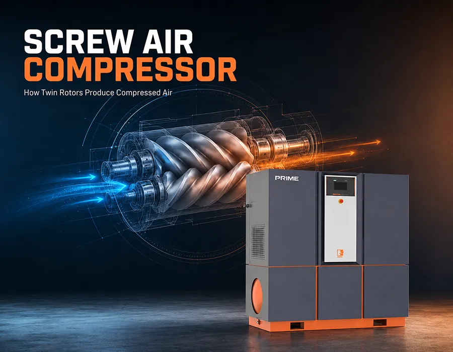
A screw air compressor is a widely used air compression device in industrial fields. It mainly consists of two meshing screw rotors, and air compression is achieved through the rotation of the rotors.
1. Classification by Number of Screws
1.1 Single-Screw Air Compressor
A single-screw air compressor is not simply a twin-screw compressor with one less screw; their operating principles are significantly different. A single-screw air compressor consists of a cylindrical screw and two symmetrically arranged planar star wheels, forming a meshing pair, housed within a main housing. The space enclosed by the screw grooves, the inner wall of the main housing, and the tooth surfaces of the star wheels constitutes the compressor’s working volume. The motor directly drives the screw shaft to rotate, and the screw in turn drives the star wheels to rotate.
Gas enters the screw grooves through the intake port on the main unit, is compressed, and then exits through the exhaust port on the main housing. The main housing also has injection holes to spray lubricating oil into the working volume, serving a sealing, cooling, and lubrication function.
1.2 Twin-Screw Air Compressors
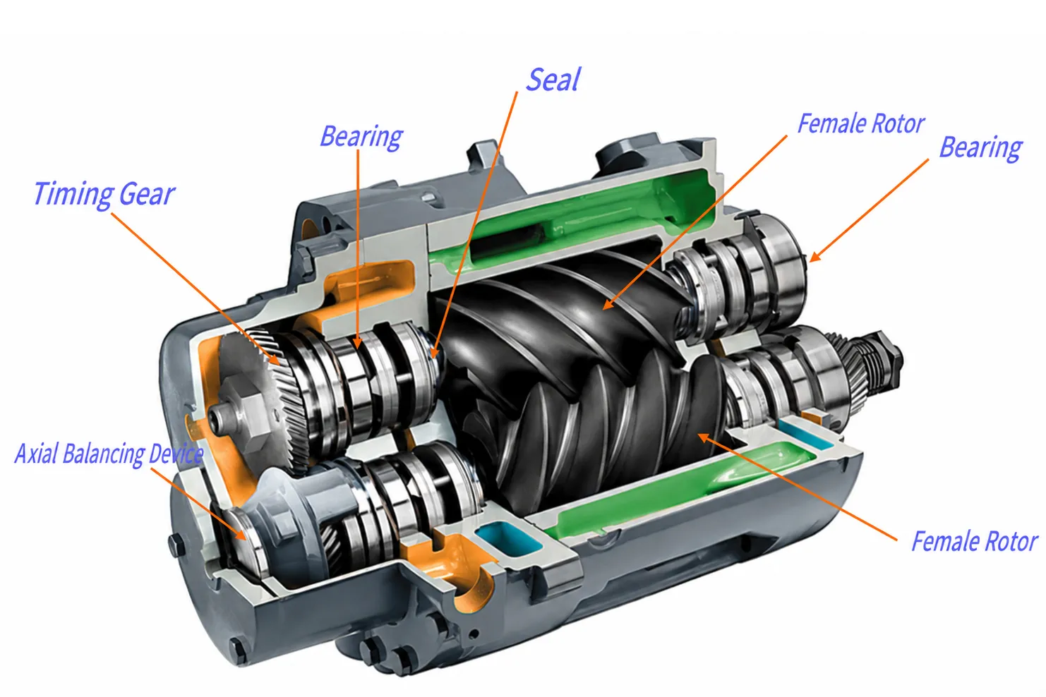
Composed of two meshing screw rotors, offering higher efficiency and more stable performance. UMW Air air compressors are all twin-screw designs.
2. Classification by Lubrication Method
2.1 Oil-Free Screw Air Compressors
Do not use oil as a lubricant. Suitable for applications sensitive to oil contamination, such as electronics and semiconductors, lithium batteries, and new energy.
2.2 Oil-Injected (Micro-Oil) Screw Air Compressors
Use oil injection for cooling and lubrication. Suitable for applications requiring lubrication, such as general machinery, CNC machining, laser cutting, injection molding, and plastics. Compared to oil-free air compressors, micro-oil air compressors have a wider range of applications. UMW Air air compressors are all micro-oil air compressors. Please contact us if you have additional needs.

3. Air Compression Process of Screw Air Compressors
The working principle of a screw air compressor mainly includes four basic processes: intake, compression, exhaust, and cooling. Air intake, compression, and exhaust are achieved through the rotation of the rotor and changes in the tooth grooves, while lubricating oil is used to reduce temperature and improve sealing.
3.1 Intake Process
When the motor drives the rotor of the screw air compressor to rotate, the space between the tooth grooves of the main and driven rotors increases as they rotate to the opening of the inlet end wall, filling it with outside air. When the inlet side end face of the rotor rotates away from the inlet of the casing, the air between the tooth grooves is sealed between the main and driven rotors and the casing, completing the intake process.
3.2 Compression Process
At the end of the intake process, the closed volume formed by the tooth peaks of the main and driven rotors and the casing decreases with the change of rotor angle and moves in a spiral motion; this is the “compression process.” During compression, the gas is continuously compressed, increasing pressure and temperature.
3.3 Compressed Gas and Oil Injection Process
During the delivery process, the volume continuously decreases, the gas is continuously compressed, increasing pressure and temperature. Simultaneously, lubricating oil, atomized due to the pressure difference, is injected into the compression chamber, achieving the functions of compression, temperature reduction, sealing, and lubrication.
3.4 Exhaust Process
When the closed tooth peaks of the rotor rotate to meet the exhaust port of the casing, the compressed air begins to be discharged until the mating surface of the tooth peaks and grooves moves to the exhaust end face. At this point, the groove space is zero, completing the exhaust process. Simultaneously, the other pair of grooves on the main and driven rotors rotates to the intake end, forming the maximum space, and the intake process begins, thus starting a new compression cycle.
4. Screw Air Compressor Related Parameters
4.1 Exhaust Pressure
The final gas pressure discharged from the compressor. Measured at the air tank for piston compressors. Measured inside the oil-gas tank for screw compressors. Rated exhaust pressure—the exhaust pressure under design conditions, i.e., the exhaust pressure marked on the compressor nameplate. The compressor can operate at any pressure below the rated exhaust pressure, and can also operate above the rated exhaust pressure as long as the strength and exhaust temperature allow. Commonly used units for exhaust pressure: bar or MPa.
For UMW Air, the air compressor exhaust pressure is between 6-25 bar.
4.2 Volumetric Flow Rate (Discharge Volume)
The volume of gas discharged from the last stage of the compressor per unit time (downstream of the aftercooler, check valve, and water separator), converted to the pressure and temperature at the first stage inlet (intake state).Volumetric flow rate (discharge volume) = Intake volume – Gas leakage.
Units of volumetric flow rate: m³/min (cubic meters per minute), L/min (liters per minute), CFM (cubic feet per minute). 1 m³ = 1000 L = 35.315 CFM. The commonly used unit for volumetric flow rate in China is m³/min (cubic meters, minutes) (standard volumetric flow rate: Nm³/min). Volumetric flow rate is also commonly referred to as discharge volume or nameplate flow rate in my country.
Different UMW Air screw air compressor series use different compression structures, such as standard process, two-stage, and horizontal two-stage. Therefore, under the same power and pressure, the discharge volume will also differ.
- Micro Series: Standard process: 0.21-1.06 m³/min; Horizontal dual-stage: 1.01-1.04 m³/min
- Prime Series: Standard process: 1.60-1.376 m³/min; Horizontal dual-stage: 2.33-3.52 m³/min; Upper and lower dual-stage: 4.17-4.20 m³/min
- Core Series: Standard process: 6.01-21.70 m³/min; Horizontal dual-stage: 5.96-6.14 m³/min; Upper and lower dual-stage: 6.02-21.07 m³/min
- Mega Series: Standard process: 25.02-70.00 m³/min; Upper and lower dual-stage: 24.96-70.00 m³/min
4.3 Pressure Dew Point
When air is cooled, the temperature at which the partial pressure of water vapor equals the saturation pressure is the dew point temperature. At this point, the air is 100% saturated with water. The dew point temperature of compressed air is also called the pressure dew point. The atmospheric dew point is the temperature at which water vapor begins to condense under atmospheric pressure (atmospheric pressure dew point). Any further cooling will result in condensation. The pressure dew point of UMW Air compressors is between 2-10℃.
4.4 Exhaust Oil Content Unit
PPM (mg/m³) The mass of oil (including oil droplets, suspended particles, and oil vapor) contained in a unit volume of compressed air, converted to atmospheric conditions of 0.1 MPa absolute pressure, 20℃ temperature, and 65% relative humidity. PPM is usually referred to as a weight ratio. (One part per million of 1 kg is a milligram) 1 PPMw = 1.2 mg/m³ (P = 0.1 MPa, t = 20℃, φ = 65%).
UMW Air filters are available in 3-stage and 5-stage configurations. Due to different filtration precision, the residual oil content also varies. A 3-stage filter corresponds to 0.01 ppm residual oil, while a 5-stage filter corresponds to 0.003 ppm residual oil.
Summary
UMW Air provides high-power, stable-supply screw air compressors to a wide range of customers. Please feel free to contact us if you have any related needs.